Yenisei UP-120
Yenisei UP-120
Description
Specifications
Download
Description
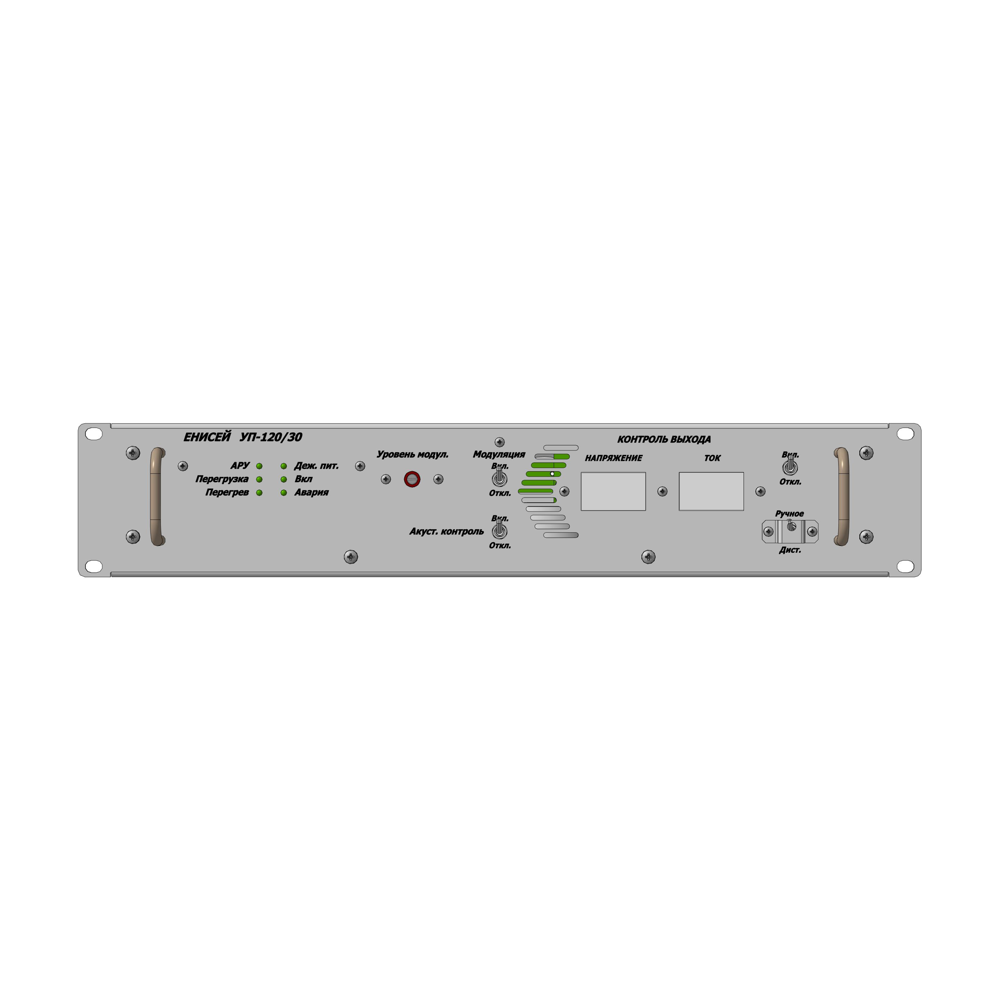
- Three-program wired broadcasting transmitter "Yenisei UP-120" is designed to convert audio broadcasting signals into amplitude-modulated signals with the carrier frequency level, adjustable according to the envelope of the audio signal and transmit them over the wired broadcasting networks.
- The Yenisei UP-120 is designed as a monoblock, 2U in height, which allows you to place device in a standard 19" rack cabinet.
- The device is powered from a single-phase AC 220V, 50Hz, with mandatory grounding.
Application:
Wired broadcasting networks
Specifications
Parameter name
Rated value
Bandwidth of transmitting frequencies
100 - 6300 Hz
Unevenness of the frequency response of the envelope
of the amplitude-modulated signal, max.
- in the frequency band from 100 to 4000 Hz inclusive
- in the frequency band above 4000 to 6300 Hz inclusive
of the amplitude-modulated signal, max.
- in the frequency band from 100 to 4000 Hz inclusive
- in the frequency band above 4000 to 6300 Hz inclusive
± 1,5 dB
от +1,5 до -3,0 dB
от +1,5 до -3,0 dB
Coefficient of harmonics of the envelope of the
amplitude-modulated signal at rated output voltage and
rated active load, max.
- in the frequency range from 100 to 2000 Hz inclusive
- when the input signal level rises by 12 dB
at 1000 Hz
- when the input signal level is reduced by 20 dB
from the rated value at 125 Hz
amplitude-modulated signal at rated output voltage and
rated active load, max.
- in the frequency range from 100 to 2000 Hz inclusive
- when the input signal level rises by 12 dB
at 1000 Hz
- when the input signal level is reduced by 20 dB
from the rated value at 125 Hz
2,5%
2,5%
2,5%
2,5%
2,5%
Protection against unweighted noise, min.
58 dB
Protection against detectable transient interference, min.
70 dB
Carrier frequency of the transmitter
120000 Hz
Rated power value of the carrier frequency
30 W
Rated value of the output voltage of the carrier frequency of the amplitude-modulated signal at the output
30 V
Modulation coefficient of the carrier frequency voltage at the rated value of the output voltage
0,7±0,05
Setting time of the output voltage amplitude-modulated signal
14-26 ms
Duration of the constant value of the carrier frequency voltage after exposure to a modulating signal, max.
20 ms
Drop time of the carrier frequency voltage
40-70 ms
Response time of automatic
gain control amplification, max.
gain control amplification, max.
3,0 ms
Amplitude-modulated signal recovery time
2±0,5 sec
Input voltage value
0,775±0,08 V
Module of impedance in the frequency range 100-6300 Hz balanced input
600±60 Ohm
Increase of the output signal level when the load is disconnected, max.
3,0 dB
Increase of output signal level when the input signal level increases by 12 dB, max
1,5 dB
Decrease of the carrier frequency signal level in relation
to the rated value at the output at the input level signal level:
0 dB
-10 dB
-20 dB
when the signal is missing on the input
to the rated value at the output at the input level signal level:
0 dB
-10 dB
-20 dB
when the signal is missing on the input
0±0,4 dB
-8±1,5 dB
-14±2 dB
-20±2 dB
-8±1,5 dB
-14±2 dB
-20±2 dB
Continuous operation time at rated load during broadcasting, min.
18 h
Harmonic coefficient, max (after a fifteen minute short-circuit
on its output at Nin = 0 dB, f = 1000 Hz and rated power)
on its output at Nin = 0 dB, f = 1000 Hz and rated power)
2,5%
Voltage value at the device output when the load resistance
is halved, min.
- for a transmitter having 30V output
- for a transmitter having 120V output
is halved, min.
- for a transmitter having 30V output
- for a transmitter having 120V output
15 V
-
-
Power consumption from AC mains 220V/20Hz, max
- at rated mode
- at an output voltage of 0.3 of rated value
- at rated mode
- at an output voltage of 0.3 of rated value
90 W
30 W
30 W
Download